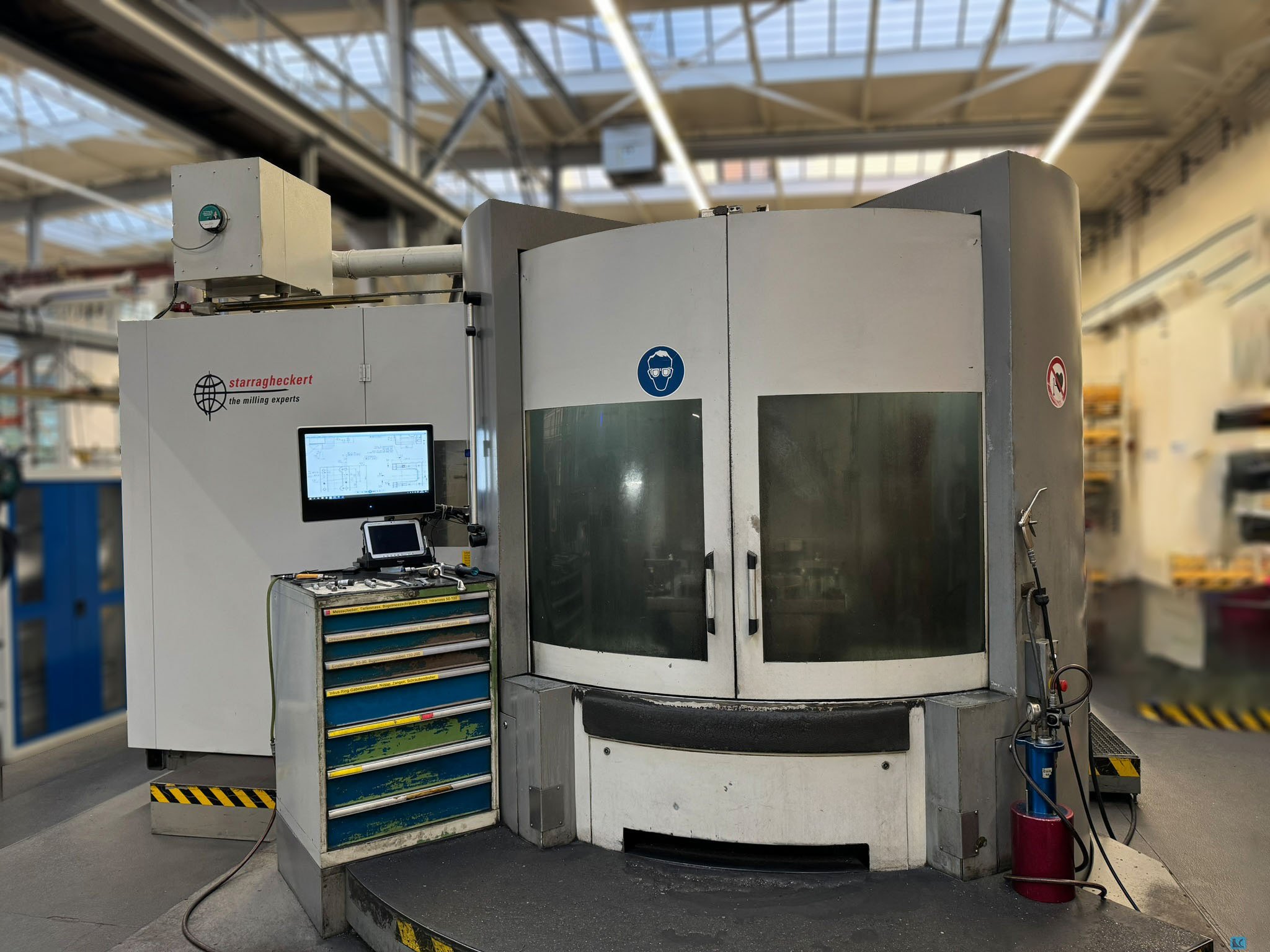
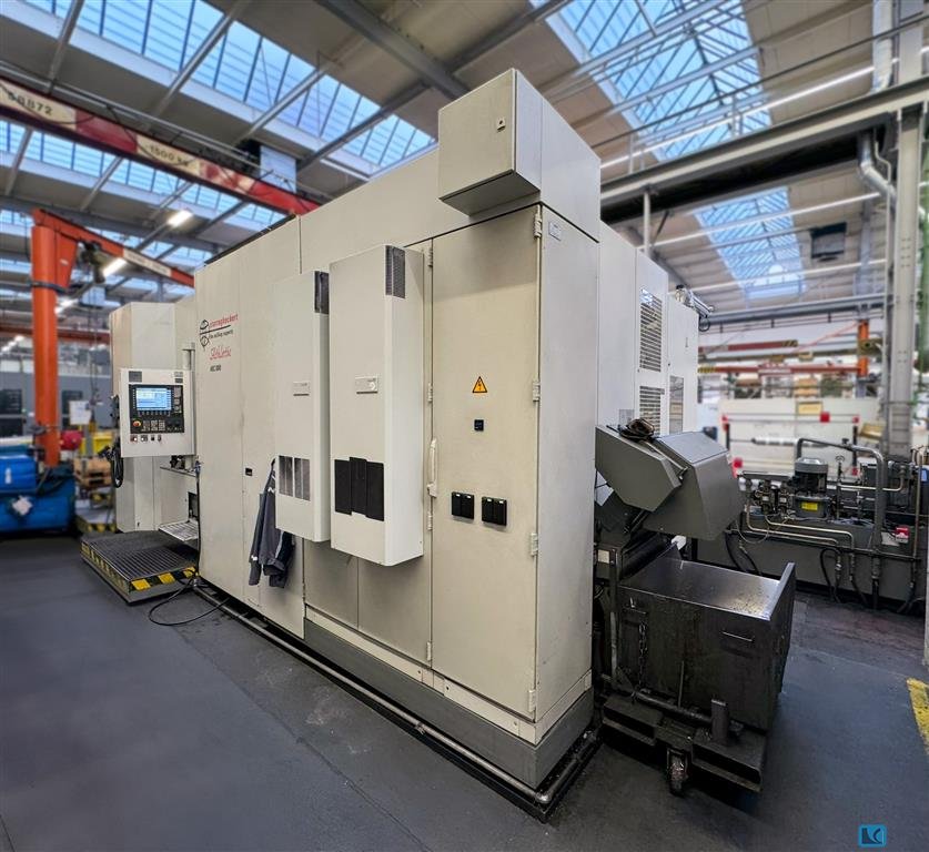
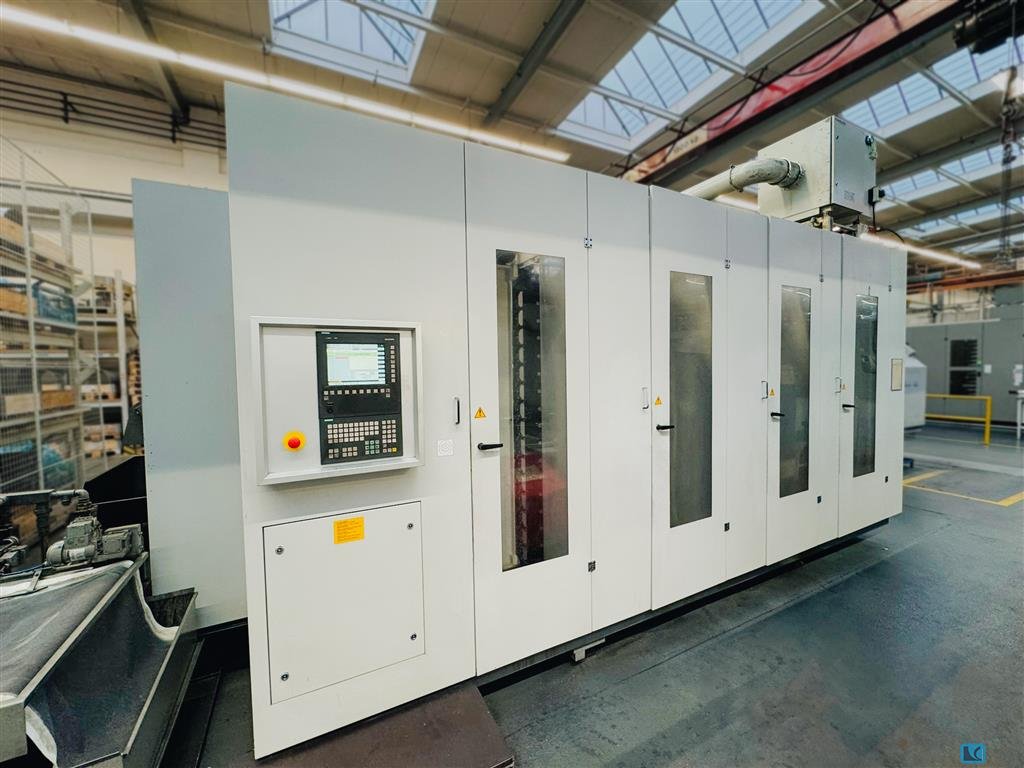
Machining Center - Universal
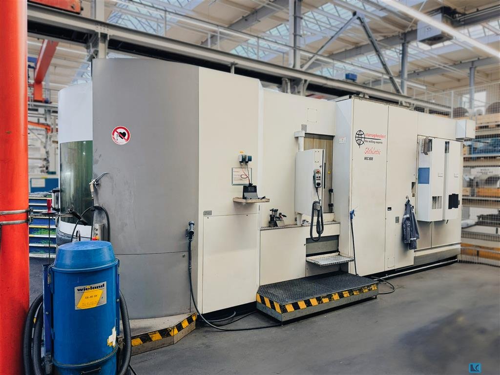
STARRAG HECKERT HEC 800 Athletic H/V
- Stock number:
- 1350-684
- Year / Condition:
- 2006 / Gebraucht
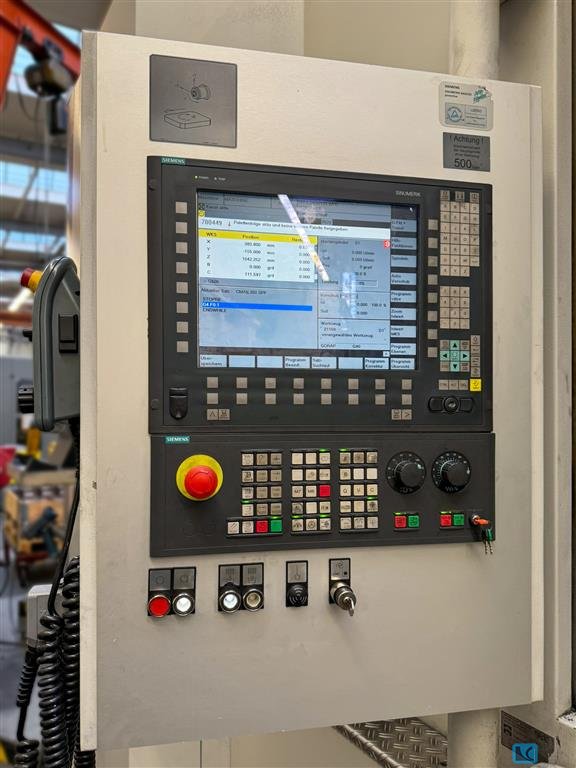
- Control unit:
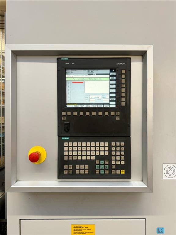
- CNC (SIEMENS 840D Solution Line)
- Country of origin:
- Germany
- Freight basis:
- Ex site
- Item location:
- Delivery time:
- Immediately

Picture / documents / videos


Technical specs
Details
- x-travel:
- 1.350 mm
- y-travel:
- 770 mm
- z-travel:
- 1.300 mm
- Input and display sensitivity b-axis:
- 0,001 Grad
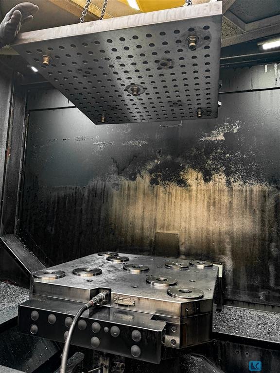
- Clamping surface/perforated pallet DIN 55201:
- 800 x 800 mm
- max. load:
- 2.000 kg
- Interference circle diameter/full circle:
- 1.600/1.400 mm
- Max. rotation:
- 60 U/min
- Drive torque:
- 2.000 Nm
- Permissible tangential moment clamped :
- 10.000 Nm
- Tangential moment for round processing:
- 2.000 Nm
- Allowable moment for off-center load:
- 10.000 Nm
- turning speed range:
- 20...6.000 U/min.
- Tool taper:
- HSK100
- Drive power 60% ED:
- 30 kW
- Drive power 100% ED:
- 28 kW
- Torque 60%ED:
- 1.080 Nm
- Torque 100% ED:
- 820 Nm
- Diamter in the front bearing:
- 110 mm
- pallet storage:
- 2 pallets
- two pallets with threaded hole:
- 800 x 800 mm
- Max. pallet changing time:
- 18 s
- max. tilting moment from OK pallet:
- 20.000 Nm
- Magazine storage slots:
- 240
- max. tool diameter:
- 250 mm
- max. tool length:
- 450 (600mm) mm
- max. tool weight:
- 35 kg
- Max. Tilting moment:
- 50 Nm
- Feed rate range of X-, Y-, and Z-axis, stepless:
- 1...60.000 mm/min
- Rapid feed for X-, Y- and Z-axis:
- 60 m/min
- Acceleration X / Y / Z:
- 6,5 / 7,5 / 5,0 m/s2
- Max. technologically usable feed forces in x, y and z-axis:
- 20 kN
- Continuous feed force:
- 18 kN
- Pressure capacity of the internal coolant supply:
- 80 bar
- coolant capacity:
- 30 l/min
- Process lubrication via nozzles, flow rate pump:
- 30 l/min
- Pump pressure via nozzles:
- 2 bar
- Total coolant quantity:
- 1.350 l
- Splash shower:
- 200 l/min
- machine dimensions LxWxH:
- 8.300 x 5.500 x 4.150 mm
- weight of the machine ca.:
- 30 t
Measuring probe RENISHAW OMP60
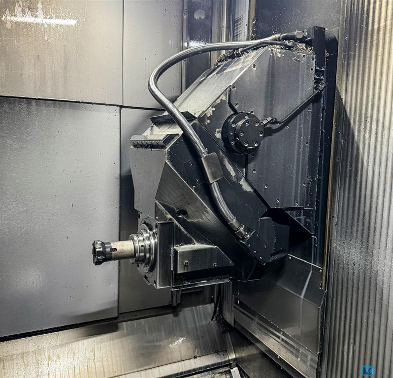
Horizontal/vertical milling head
Tool turret with 240 stations in 4 towers, with integr. 2nd NC control panel
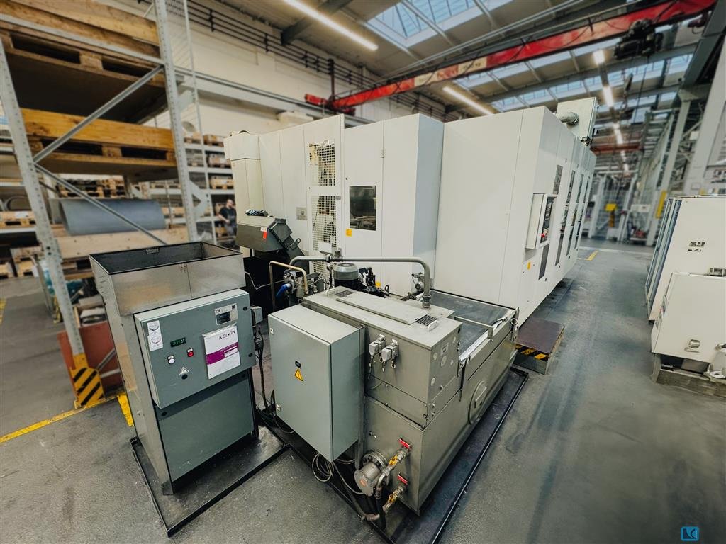
Coolant unit Fleece gravity filter
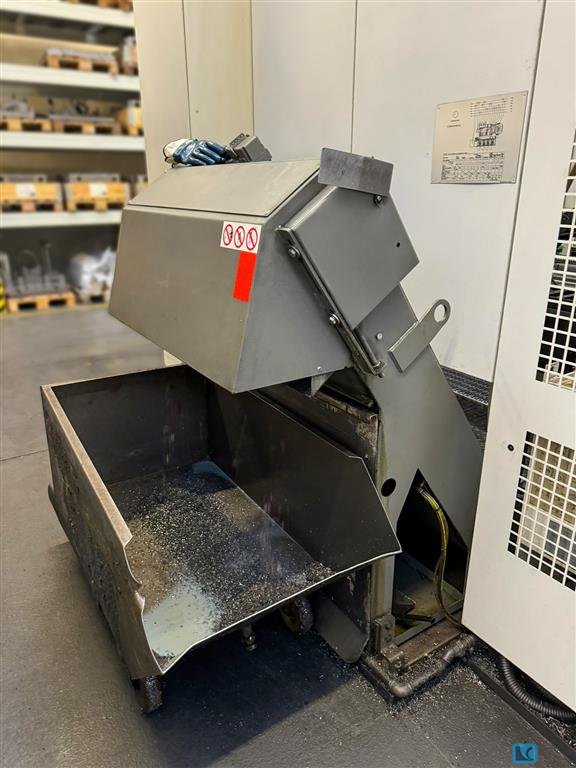
Chip conveyor KNOLL 1000K-3, Discharge height:
NC rotary table
Two pallets with threaded hole
Flush gun at the set-up site
Splash shower
Electronical hand wheel
2-fold pallet changer
Tool breakage check in the base tool turret using pneumatic cylinders
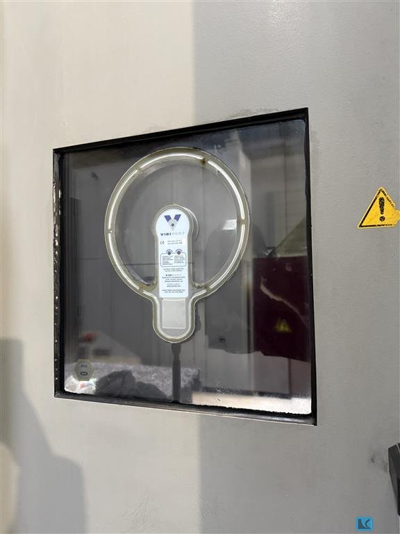
Visiport electrically rotating viewing window in the workspace door
Oil and emulsion mist extraction
HECVIEW data recorder
Description
HISTORY OF THE MACHINE
First owner of the STARRAG HECKERT HEC 800 Athletic universal machining center is a renowned German manufacturer of large diesel engines and turbomachinery for maritime and stationary applications. The company is known worldwide for its high quality standards.
The machine was used to manufacture all cubic components for large diesel engines, such as rocker arms, camshaft bearings, crankshaft bearing caps, valve bridges, bearing blocks, exhaust pipes, charge air pipes and bearing housings.
The machine is in good condition and still produces very accurately. The machine was only sold for strategic reasons. The components manufactured on this machine were distributed to other machines, for this reason orders can also be placed with the new owner for these same owners.
The machine produces tolerances in the H6 range, even with large diameters up to 210mm H6 was no problem. The previous owner was always able to produce positional accuracies on drawings of 0.02 mm to various reference elements on the drawings and with the same repeat accuracy.
Parallelism of 0.02 mm and perpendicularity of 0.02 mm to distant surfaces were also required of the components.
Various cast materials such as EN-GJL-300, 400, 500 or even SiMo cast iron, but also rolled material such as ST52 or many forged parts, many of them 42CrMo4-QT, were processed on the machine.
According to the previous owner, a major inspection/maintenance was always carried out once a year, so there was no maintenance backlog.
The horizontal/vertical milling head was last replaced in May 2018 (runtime CSP12.409// DDF 1339). A measurement report from the last inspection in 2024 is available and can be sent on request.
Machine structure:
The basic machine consists of the following main assemblies
Cross bed
Frame stand
Frame stand support in the HV version
Rotary table
Feed drives, guides, measuring systems
Tool changer
Tower magazine
Pallet changer
Work area protection and cladding
Cooling lubricant unit and chip conveyor
Equipment for auxiliary processes: Hydraulics, pneumatics, lubrication, chip disposal and cooling
Numerical control
CROSS-BED
The cross-bed forms the statically and dynamically rigid lower section, which is connected to the foundation via adjusting wedges and anchor bolts.
On the cross bed there are fixed stops, profile rail guides, feed drives, ball screw drives and measuring systems for the X (frame upright) and Z (rotary table) axes.
The Z guide is protected by fixed plate covers. The X guide is located outside the working area behind traveling vertical link aprons.
Other assemblies attached to or on the cross bed are
- Tool changer frame
- Console with hydraulic unit and energy tower
- Energy supply to the turntable
- Work area guard
FRAME STAND
The frame stand moves on the X-guide of the cross bed. The Y-guideway consists of a profile rail roller guide that is bolted to the front of the stand. The feed drive for the Y-axis is attached to the top of the stand and connected to the ball screw, the nut of which is attached to the support. The mass of the support is compensated by a hydraulic counterbalance. A measuring system is located at the front of the stand for direct travel measurement. The upward and downward travel is limited by fixed stops. All components on the front of the stand are protected by covers.
ROTATING TABLE
This machining center is equipped with a rotary table. The rotary table is located on the Z-slide, which moves on the profile rails of the Z-axis. The spindle nuts of the ball screws and the sliders of the measuring systems are attached to the Z-slide. The interior of the rotary table is pressurized with sealing air to prevent the ingress of foreign particles such as dirt and cooling lubricant. The pallet is picked up, fixed and hydraulically clamped on conical clamping heads. When changing pallets, the clamping and fixing surfaces are cleaned with compressed air.
HV-SUPPORT
The H/V Support consists of the guide section, the intermediate section with swivel head and the bolted-on main gearbox.
It contains the following functional groups:
- Gearbox with speed control
- Drive train with bevel gears
- Swivel head with working spindle and bearing Hydraulic swivel device
- Rotary feed-through for media
- Tool clamping
- Work spindle straightening device
The two-stage main gearbox is driven by an AC motor and switched via a pneumatic cylinder. The swivel head with work spindle and intermediate piece are connected to the gearbox by means of a backlash-free coupling.
Both units can be disassembled and assembled on the machine without having to separate the support from its guide and feed spindle.
The work spindle is aligned electronically via a measuring system for tool changes and the position of the taper holder.
The tool is clamped by a clamping device in which the tool is pulled into the taper using collets via disk springs.
When the "tool clamped"Â position is reached, this status is signaled. If the tool is incorrectly clamped, e.g. clamping claws on the collar of the tightening bolt, no "tool clamped" signal is given.
The tools are released hydraulically by a piston pushing the tightening rod forwards against the spring force of the disk springs, causing the clamping claws to swing out and the tool shank to be ejected from the work spindle.
During tool change, the following switching states are indicated by signals from an analog initiator:
- Tool released
- clamped with tool
- clamped without tool
Before the tool is changed from the work spindle, the cooling lubricant remaining in the feed-through elements and in the tool is blown out. This compressed air is also used to clean the work spindle cone during the change. The gearbox recirculating lubrication system is arranged as an independent unit on the support.
The horizontal or vertical position of the support is generated by a hydraulic swivel device with rack and pinion. The swivel head is clamped and lifted hydraulically. Rings with Hirth serration ensure positioning.
COOLING LUBRICANT SUPPLY ON THE WORK SPINDLE
There are two options for supplying the cooling lubricant to the work spindle of the basic machine
- Cooling lubricant through the center of the work spindle
- Cooling lubricant through nozzles.
Both variants can be integrated together or individually into the machining programs.
COOLING LUBRICANT THROUGH THE WORK SPINDLE
A high-pressure pump delivers the cooling lubricant to the tool via a rotary feed-through through the work spindle.
A pressure relief valve and a flow monitor are integrated into the line from the pump to the work spindle.
Cooling lubricant through nozzles
A low-pressure pump feeds the cooling lubricant to the nozzles on the work spindle.
feed, guides, measuring systems
DRIVES
The X, Y, Z1 and Z2 axes are driven by digital AC servomotors via toothed belts on preloaded ball screws for the assemblies:
- Frame stand
- Support with work spindle
- Z-slide with table assembly as gantry drive
The drive motors are arranged externally for easy servicing. They are located on the side of the
- frame upright on the side of the X-bed
- the table on both sides of the Z-bed
- Support on the frame upright
The travel paths of the linear axes are limited by software limit switches and protected by fixed stops.
All profile rail guides, axis drives and measuring systems mounted in or on the work area are protected by covers and are sealed against cooling lubricant and chips.
GUIDES/ BALL SCREW DRIVES
Pre-tensioned and precisely aligned profiled rail roller guides ensure high precision of the assembly guides and thus high machining quality and long-term accuracy.
In conjunction with the double-sided bearings, the clamped ball screws ensure high rigidity of the linear motion axes.
MEASURING SYSTEMS
The length measurement in the x, y and z axes is carried out by means of a direct absolute length measuring system.
They are encapsulated in an aluminum housing and are supplied with compressed air. This means that the scanning carriage and its guide are optimally protected against chips, dust and splash water.
An incremental, encapsulated angle measuring system is used for the rotary table.
For the work spindle (C-axis), the angle is measured via an incremental rotary encoder and electronic evaluation.
This axis positions the angular position of the tool (tool change, thread cutting, shaping, angle-defined removal from the workpiece).
It is driven by a hydraulic motor.
At the loading station, the tools are manually pressed into the plastic tool holders of the tool chain. To remove them from the loading station, the tools are unlocked with a pneumatic cylinder.
PALLET CHANGER
The pallet changer is designed as a hydraulically driven rotary changer. It changes the pallets between the work area and the set-up station area by means of the rotary movement.
Pallet Changer
To change pallets, the pallet in the working area must be brought into the pallet change position. The pallet on the setup station must be positioned at 0°. Then the pallet clamping on the rotary or indexing table is released. Next, the pallet changer is raised hydraulically, gripping both pallets, rotating them 180°, and lowering them again.
During the pallet change cycle, the pallet seats are blown off. The pallet change is only carried out when the setup station door is locked. The pallet on the setup station can be rotated manually and locked in four 90° positions.
Machine Enclosure for the Working Area
The working area of the machining center is an all-around enclosed cabin providing:
- Protection for the operator
- Protection of the environment from chips and coolants
- Noise reduction
Working Area
A vertically lifting door separates the working area from the tool changer. Toward the main operating station, a locked sliding door with a viewing window secures the operator's position. In setup mode, this sliding door can be opened by hand, enabling better observation of the machine's functions.
Turret Magazine
This patented tool magazine for 240 tool stations (4 turrets) is an assembly that is set up directly adjacent to the machine (instead of a chain-type tool magazine) and aligned with it.
The turret magazine is a particularly space-saving design for holding a large number of tools. Each tool turret takes the shape of a prism with a square cross section. Along each of the four vertical edges, there is a tool rack running the full height, each containing 15 tool stations.
The turret magazine consists of the following components:
- Loading Station
On each turret, one of the racks is accessible from the outside through a door for inserting or removing tools.
- Base Frame
The four tool turrets are mounted to rotate within the base frame. The guides and drives for the feeder are also installed on this base frame.
- Tool Turrets
Each turret accommodates four racks, each with 15 tool stations. For tools longer than 450 mm up to 800 mm, turret 1 has only three racks with 15 stations each. Of these, 15 tool stations can hold tools over 450 mm in length.
- Tool Feeder
It transports the tools from the rack to the tool changer and features a toothed belt drive for the Q-axis (horizontal movement, parallel to the machine's secondary axis) and the V-axis (vertical movement, parallel to Y), as well as a feeder arm (which hands the tool over to the tool changer).
- NC Control Panel
Tool Dimensions
- Max. diameter (with free neighboring stations): 250 mm
- Max. diameter (with occupied neighboring stations): 110 mm
- Max. overhang length: 450 mm
- Max. tool weight: 35 kg
- Max. tilting moment (at the gripping point of the base holder): 50 Nm
- Max. total weight of all tools per turret: 600 kg
Turret Magazines with Oversized Tools
Tool length of 800 mm in the turret magazine
Storing tools with lengths over 450 mm and up to a maximum of 800 mm is possible for 15 storage locations. As a result, the total number of storage slots is reduced by 15.
Probe
By using a probe, you can perform various measuring tasks when setting up workpiece machining and during machining programs. Use the measuring cycles offered by the control manufacturer! The probe is treated like a tool. The NC control recognizes when the probe is in the working spindle.
The probe can perform the following tasks:
- Determination of the workpiece zero point
- Workpiece detection
- Indirect tool breakage control by probing machined surfaces
- Measurement of actual dimensions of bores, shafts, surfaces, etc.
An optical transmission probe is used. Switching the probe on and off is carried out by an optical signal triggered by the NC control.
Tool Breakage Control
Using the drill breakage control, drilling tools can be checked "Âwithin the machining program" or maintaining their original length.
SPINDLE VARIANT
Horizontal/Vertical Milling Support
Working Spindle
- Front bearing diameter: 110 mm
- Spindle speeds: 20 - 6000 rpm
- Tool interface: HSK-A100
Coolant Supply
- Increase of coolant pressure to 80 bar for process lubrication through the spindle center with an HSK 100 tool holder.
- Only in combination with a coolant unit featuring a vacuum rotation filter or a coolant unit with a fleece gravity filter.
- Connection to a central coolant system
- The interface is the discharge side of the return pump on the chip conveyor or the coolant supply line to the machine's coolant unit
ADDITIONAL EQUIPMENT
- Working Area Emission Extraction:
A mechanical filter system is installed in the working area, providing continuous air cleaning to 99% (cleanroom quality, filter class EU13 according to DIN EN 1822).
- Visiport:
An electrically rotating viewing pane in the working-area protective door at the main operating station.
CONTROL AND MONITORING DEVICES
- Renishaw Probe Interface consisting of the receiver module and milling measuring cycles
- Renishaw Measuring Probe and controller-based use of the probe
- Tool Breakage Control outside the working area
- 4-Color Signal Lamp to indicate machine status:
oRed: Machine out of operation
oGreen: Machine running in automatic mode
oYellow: Locked or pre-warned tools in the magazine
oWhite: Workpiece machining completed
Key Advantages of the Horizontal/Vertical Milling Head
- 5-side machining in a single setup
- Highest dynamic performance for both positioning and simultaneous operation
- High concentricity accuracy thanks to quadruple precision bearings
- Hirth ring coupling ensures extremely precise swivel positions
- Automatic compensation of axial spindle expansion under thermal load, as well as through-bore compensation
Chip Management
For reliable, rapid chip removal and to protect all functional components, the gantry design allows chips to flow freely to the centrally located chip conveyor. This design prevents chips from accumulating in the working area. Fixed panels further protect the machine's functional elements from chips and coolant.
Contact seller
LüneHanse Vertriebs GmbH
Munstermannskamp 121335 Lüneburg Phone: +49 4131 21 97 689Fax: +49 4131 21 97 290
